Red light therapy flicker is a change in optical output over time. It can be obvious, visible pulsing, or a rapid modulation that looks continuous to the eye. A phone camera may show dark bands, yet another camera may show nothing. A device may advertise “flicker-free” without explaining the test method. These mixed signals make the specification difficult to evaluate.
This guide explains temporal light modulation, frequency, modulation depth, duty cycle, and waveform measurement. It also separates unintended driver ripple from deliberately pulsed photobiomodulation. The two can produce similar-looking graphs, but they are not automatically equivalent in purpose, exposure, or evidence.
What Flicker Means in an LED Device
The International Commission on Illumination uses the term temporal light modulation (TLM) for measurable changes in light level or spectral distribution over time. “Flicker” is often used casually for both the stimulus and what a person perceives, but the distinction matters. A light can modulate without looking visibly unstable, and visual responses depend on the waveform, frequency, modulation depth, viewing conditions, movement, and individual sensitivity.
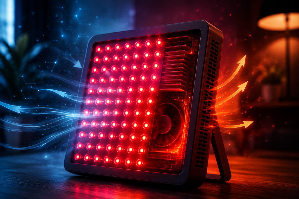
LEDs respond quickly to changes in current. If the driver supplies uneven current, the optical output can follow that variation. Modulation may come from rectified mains electricity, a power supply, a dimming circuit, pulse-width modulation, control electronics, or a deliberate pulsing mode.
Unintended Flicker Versus Intentional Pulsing
Unintended temporal modulation
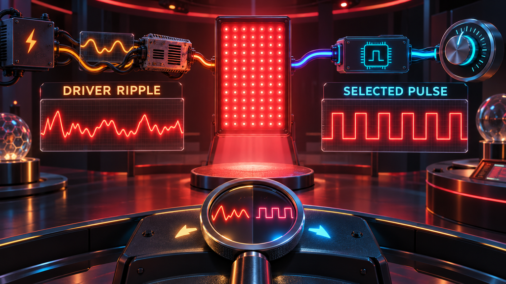
Unintended flicker is usually a by-product of the electrical design. A driver may allow current ripple at twice the mains frequency or introduce switching components at higher frequencies. Dimming can change the waveform or increase the percentage modulation. The device may not label this behavior because it is not a user feature.
Intentional pulsing
Some red light therapy devices intentionally switch output on and off at a selected frequency. Manufacturers may describe this as pulsing, pulse-width modulation, or a frequency setting. A complete description requires more than hertz: it should include duty cycle, pulse width, peak irradiance, time-averaged irradiance, and waveform.
A deliberately pulsed mode is not inherently superior to continuous output. The existing article on pulsing versus continuous light reviews that separate research question. Here, the focus is how modulation is described and measured.
Frequency: How Often Output Repeats
Frequency is the number of cycles per second, measured in hertz (Hz). A 100 Hz waveform repeats 100 times each second. A 1 kHz waveform repeats 1,000 times per second. Frequency alone cannot describe the severity or visibility of modulation. A shallow sinusoidal variation and a full on-off square wave at the same frequency are different stimuli.
Directly visible flicker is generally associated with lower frequencies, but higher-frequency modulation can produce stroboscopic or phantom-array effects during motion. The Pacific Northwest National Laboratory review by Miller and colleagues describes direct flicker effects below roughly 80 Hz as comparatively well understood, with motion-related artifacts occurring above that range. These are lighting-science observations; they do not establish a clinical outcome for a specific red light therapy device.
Modulation Depth: How Large the Change Is
Modulation depth describes the size of the variation relative to the maximum and minimum output. One common percentage formula is:
Modulation depth = (maximum − minimum) ÷ (maximum + minimum) × 100
If output alternates between full intensity and zero, the modulation depth is 100%. If it varies only slightly around a steady level, the value is much lower. The exact metric and convention should be stated, because terms such as percent flicker and modulation percentage are not always used consistently.
Frequency and modulation depth must be considered together. IEEE 1789-2015 discusses both when providing recommended practices for current modulation in high-brightness LEDs. The standard was developed for LED lighting viewed by people, not specifically for therapeutic panels, so it should not be misrepresented as a red light therapy efficacy standard. It is relevant when evaluating the temporal behavior of bright visible LEDs.
Duty Cycle and Pulse Width
Duty cycle is the fraction of each cycle during which the source is on. At a 50% duty cycle, it is on for half the cycle and off for half. At 10%, it is on for one tenth of each cycle.
Pulse width is the duration of an individual pulse. Frequency and duty cycle are mathematically connected to pulse width. At 100 Hz, one complete cycle lasts 10 milliseconds. A 50% duty cycle produces a nominal 5-millisecond on-time. At 1,000 Hz, a cycle lasts 1 millisecond, so the same duty cycle produces a 0.5-millisecond pulse.
Duty cycle affects average output. If the instantaneous irradiance is 100 mW/cm² while on and the duty cycle is 50%, the ideal time-averaged irradiance is 50 mW/cm², assuming clean rectangular pulses and stable amplitude. A device can advertise the peak or the average; the report must identify which one.
Waveform Shape Matters
Real waveforms are not always perfect square waves. They can be sinusoidal, triangular, clipped, asymmetric, or made of several frequency components. Rise and fall times may be gradual, and the “off” state may retain some output. Power supplies can add high-frequency ripple on top of a lower-frequency pattern.
Two devices can share the same fundamental frequency and modulation depth while producing different waveforms. Lighting metrics compress those details into useful summary numbers, but the original time-domain trace and frequency spectrum remain valuable for technical comparisons.
CIE guidance describes both time-domain and frequency-domain approaches to temporal light artifacts. A careful red light panel report should preserve the waveform rather than stating only “zero flicker” or “10 kHz.”
Why Phone-Camera Tests Show Bands
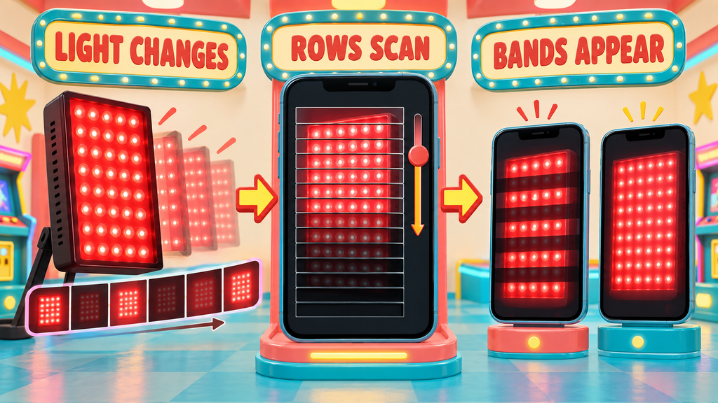
Many phone cameras use a rolling shutter: different image rows are exposed at slightly different times. If light output changes during that scan, the video can display moving dark or bright bands. Shutter speed, frame rate, exposure, anti-banding settings, camera model, and the modulation frequency all affect the result.
Bands are evidence that the camera and light interacted temporally, but they do not quantify modulation depth or provide a reliable frequency without a controlled method. Their absence does not prove flicker-free performance. The camera may simply be sampling at a setting that hides the waveform.
Slow-motion video can be a screening tool. It is not a substitute for a fast photodetector and oscilloscope or a purpose-built temporal light meter.
How Flicker Is Measured Properly
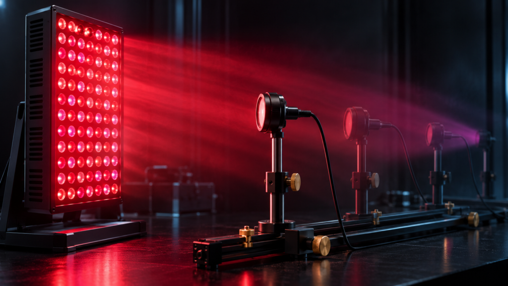
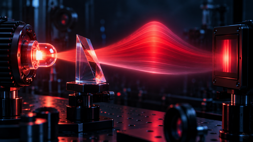
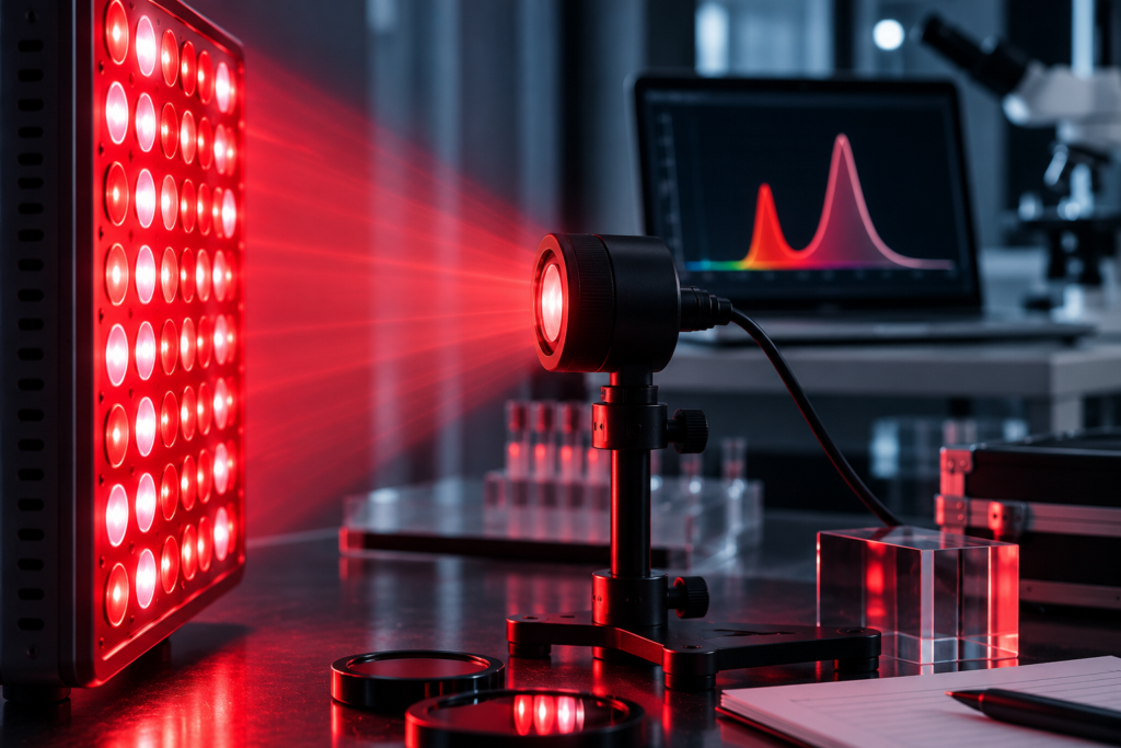
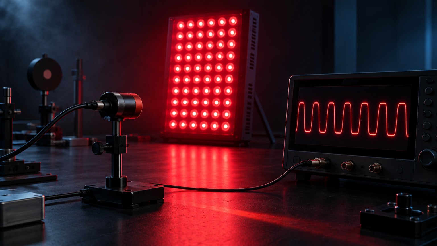
A measurement system typically uses a photodetector fast enough to follow the light, electronics with adequate bandwidth, and an oscilloscope or data-acquisition system. The sampling rate must be high enough to capture the waveform and its relevant harmonics. The detector must respond to the wavelength being tested.
- Record device settings. Note output level, dimming level, wavelength channels, pulse mode, and warm-up time.
- Measure channels separately when possible. Red and near-infrared emitters may use different drivers or modulation schemes.
- Fix geometry. Keep the detector position, distance, angle, and aperture constant.
- Capture sufficient time. The trace should contain enough cycles to reveal low-frequency components and irregular behavior.
- Use sufficient bandwidth and sampling. A slow sensor can smooth rapid modulation and falsely make output look steady.
- Report the waveform. Include frequency, maximum, minimum, modulation depth, duty cycle, and whether irradiance is peak or time averaged.
- Repeat at different output levels. Some drivers behave differently when dimmed.
CIE TN 012:2021 provides guidance for measuring temporal light modulation in light sources and lighting systems. While consumer therapy panels are not ordinary room lamps, the measurement principles are more defensible than an undocumented camera test.
Near-Infrared Flicker Is Invisible to the Eye
Near-infrared output cannot be evaluated by looking at the panel. A camera may detect some near-infrared wavelengths, but camera filters and automatic processing vary widely. A photodetector with suitable spectral response is required.
This is one reason combined-channel measurements can be misleading. A visible red channel may be steady while a near-infrared channel is modulated, or vice versa. A meter that measures only total combined output can hide that difference unless each channel is tested independently.
Flicker Metrics and Their Limits
Percent flicker or modulation depth
This is easy to understand but ignores frequency and waveform shape. It should not be used alone to rank devices.
Flicker index
Flicker index considers areas of the waveform above and below the average light level over a cycle. It captures more shape information than a maximum-minimum percentage but still does not fully predict every visual artifact.
PstLM and SVM
Short-term flicker indicator (PstLM) and stroboscopic visibility measure (SVM) are established metrics used in lighting standards and regulation for particular perceptual effects. Applying them to a therapy device requires appropriate measurement conditions and careful interpretation. They are not measures of photobiomodulation effectiveness.
What “Flicker-Free” Should Mean
“Flicker-free” is incomplete without a detection threshold, bandwidth, settings, and test method. No instrument has unlimited sensitivity or frequency range. A transparent claim might state that no modulation above a specified percentage was detected from a stated lower frequency through the instrument bandwidth at full output and at each dimming level.
Consumers should ask whether the red and near-infrared channels were measured separately, whether the device was tested at reduced intensity, and whether the result refers to temporal modulation or simply to visible flicker. A low-quality driver can look stable to the eye yet show substantial modulation on an instrument.
Does Flicker Change the Delivered Dose?
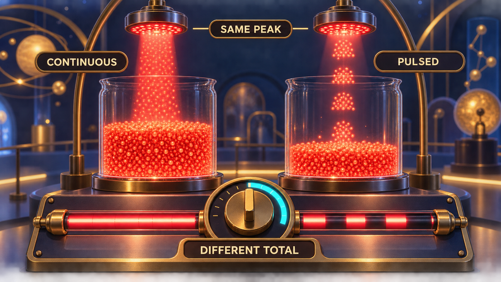
It can. For a modulated source, radiant exposure depends on time-averaged irradiance, not only the instantaneous peak. If two devices share the same peak but one is off half the time, their average surface exposure differs unless the pulsed device compensates with a higher peak.
Our irradiance and dosage guide explains the basic relationship between irradiance and time. For pulsed output, the correct average must account for the waveform and duty cycle. Multiplying peak irradiance by the entire session time overstates energy when the light is not continuously on.
Health Claims Require Careful Boundaries
Lighting research and standards discuss visual discomfort, headaches, migraine episodes, stroboscopic effects, and photosensitive seizure risk under certain temporal-light conditions. Device geometry, brightness, spectrum, exposure, viewing behavior, individual sensitivity, and modulation all matter. Evidence from general lighting cannot be converted into a precise risk threshold for every red light therapy panel without product-specific assessment.
People with photosensitive epilepsy, migraine triggered by light, significant eye conditions, or unusual symptoms during use should stop and seek individualized medical guidance. Users should follow the device’s eye-safety instructions. A “flicker-free” marketing label is not a substitute for safety documentation.
Questions to Ask a Manufacturer
- Is temporal light modulation measured on the red and near-infrared channels separately?
- What detector, sampling rate, and bandwidth were used?
- What are the dominant frequencies and modulation depths?
- Does the waveform change at lower brightness settings?
- For pulse modes, what are the duty cycle, pulse width, peak irradiance, and average irradiance?
- Can the company provide a time-domain waveform rather than a single badge?
- Does “flicker-free” mean no visible flicker or no detected modulation within stated limits?
How Flicker Fits Into a Device Comparison
Temporal performance is one part of device quality. Wavelength accuracy, irradiance at a stated distance, coverage uniformity, thermal stability, electrical safety, controls, warranty, and mechanical construction also matter. The device buyer’s guide explains how to compare these specifications without treating any single number as decisive.
A good test report makes the device easier to understand. It does not promise better clinical results merely because a waveform is smooth or a pulse frequency is selectable.
Conclusion
Red light therapy flicker is better described as temporal light modulation: optical output changing over time. Frequency tells you how often the waveform repeats; modulation depth tells you how large the change is; duty cycle and pulse width describe on-time; and the waveform shows what the light actually does.
Phone-camera bands can flag modulation but cannot quantify it reliably. Look for measurements from a suitable photodetector, adequate sampling, separate wavelength channels, multiple brightness settings, and a published trace. Most importantly, distinguish unintended driver ripple from deliberate pulse modes, and do not confuse a temporal-light metric with evidence of therapeutic effectiveness.