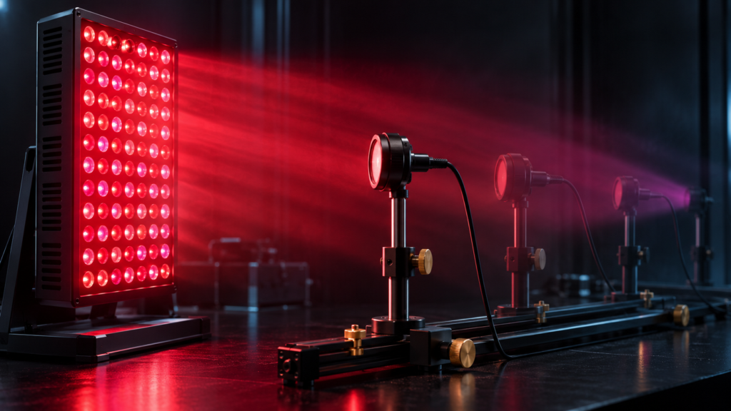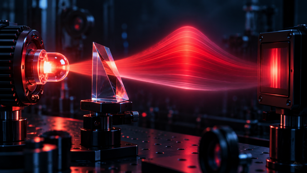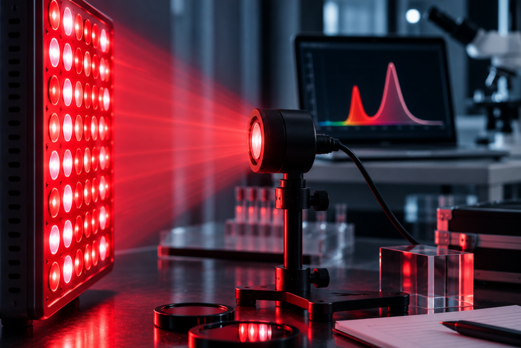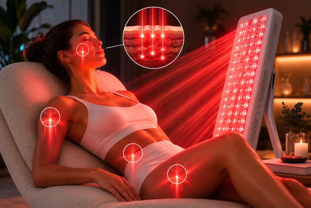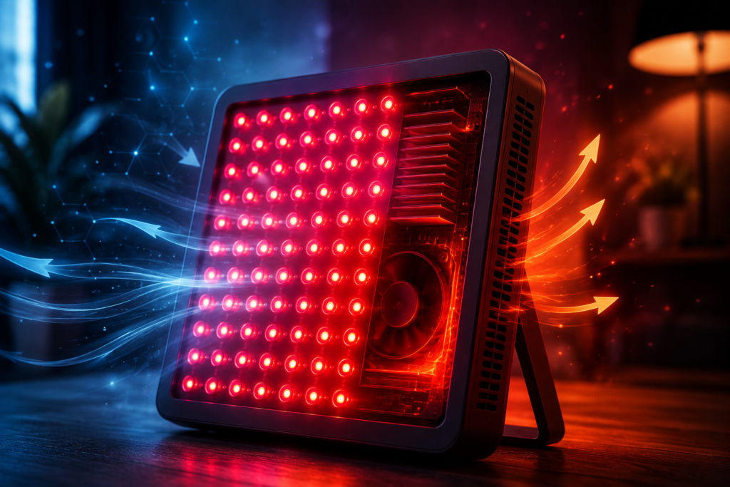
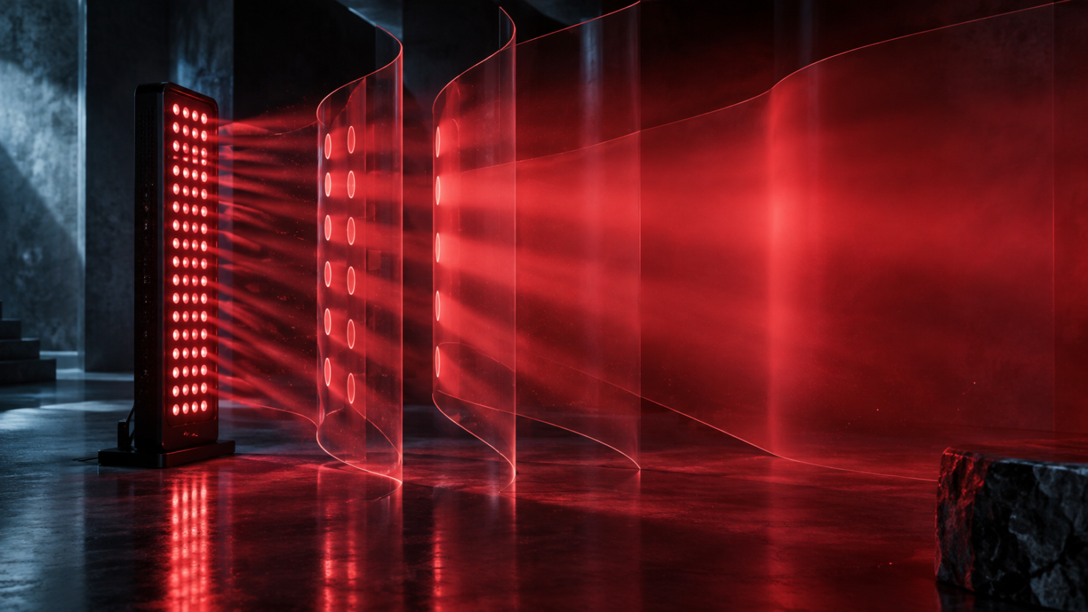
Beam angle is one of the least understood specifications on a red light therapy panel. It helps describe how widely each LED lens spreads light, but it does not tell you the treatment area, dose, or penetration depth by itself. The useful question is how beam angle interacts with LED spacing, distance, and the overlapping output of the entire array.
This guide explains what beam angle means, why narrow and wide lenses create different coverage patterns, and how to compare panels without mistaking a bright center reading for uniform treatment coverage.
What Beam Angle Means
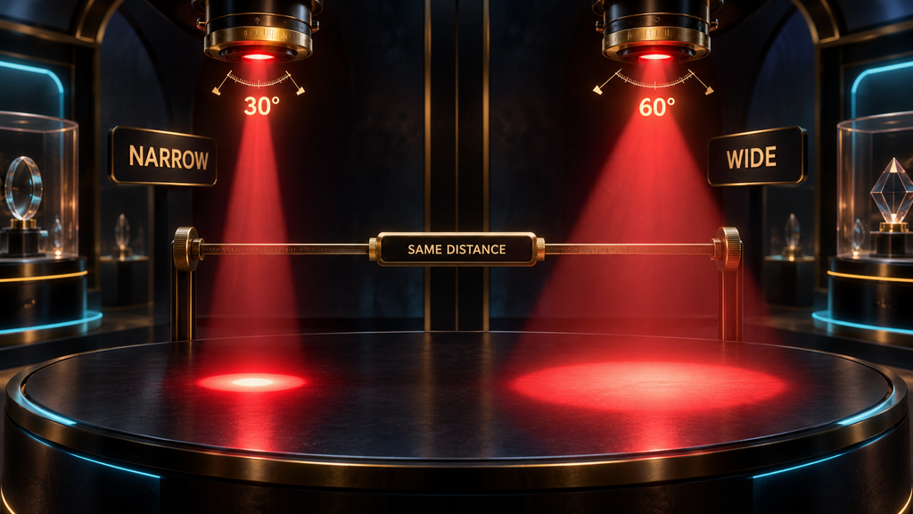
For an LED, beam angle describes the angular width of emitted light under a stated intensity convention. It is commonly associated with full width at half maximum: the angle between points where intensity falls to half the on-axis value. It is not a hard boundary; useful light does not abruptly stop at the quoted angle.
A nominal 30-degree lens concentrates more output near the forward axis than a 60-degree lens under otherwise similar conditions. The wider lens spreads light across a larger area sooner, usually lowering the central peak. In a panel, dozens or hundreds of these distributions overlap.
Why One LED Does Not Describe a Whole Panel
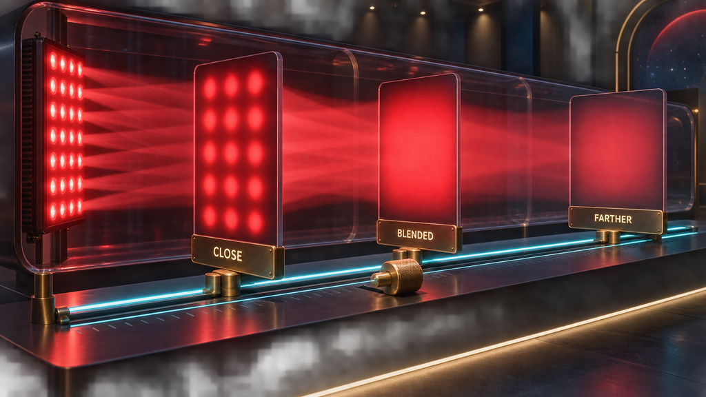
A panel is an extended source, not one point light. Overall coverage depends on LED count, row spacing, lens geometry, panel dimensions, wavelength channels, and treatment distance. Close to the face, individual hot spots and darker gaps may remain. Farther away, neighboring beams overlap and the field becomes smoother while irradiance generally declines.
Peer-reviewed calibration work on commercial LED arrays has shown that spatial output can vary substantially across an illuminated field, and the maximum is not necessarily at the geometric center. A single reading cannot establish uniformity.
Narrow and Wide Beam Angles: The Practical Trade-Off
A narrow lens is often marketed as “deeper” or “more powerful,” while a wide lens is described as better for coverage. Those statements are incomplete. A narrow lens can create a higher on-axis irradiance at a given distance because more of the emitted power is concentrated into a smaller angular region. That does not establish deeper biological delivery by itself. Wavelength, surface irradiance, tissue optical properties, spot size, and the geometry of the target all affect how light is distributed.
A wider beam can illuminate a larger surface area from a short distance and may allow adjacent LEDs to blend sooner. The trade-off is that the same radiant power is distributed across a broader field, so the central peak is generally lower. Neither design is universally better. A small targeted device and a full-body panel solve different placement and coverage problems.
Marketing comparisons are unreliable when one company reports a narrow-beam peak and another reports an average across a wider area. Lens angle should be evaluated alongside a spatial irradiance map measured at the intended treatment distance.
Distance Changes the Pattern, Not Just the Number
The existing treatment-distance guide explains that irradiance usually falls as the user moves away from a panel. Beam angle adds another layer: distance also changes how much the individual LED fields overlap.
Very close to an array, the skin may sit inside separate cones from individual emitters. A meter moved a few centimeters sideways can pass from a bright point to a darker gap. At a moderate distance, those cones expand and overlap, making the field more uniform. At still greater distances, the panel may cover more of the body, but the average irradiance continues to decline.
This is why a manufacturer can legitimately recommend a distance that is not the point of maximum central irradiance. The recommended position may balance output, comfort, coverage, and uniformity. Sitting closer is not automatically an upgrade.
Why the Inverse-Square Law Is Only an Approximation for Panels
The inverse-square law describes how irradiance from an ideal point source spreads through space. A large LED panel is not a point source, particularly when the user is close to it. Each LED has its own position and angular distribution, and the detector receives light from many emitters at once.
At sufficiently long distances, the array can behave more like a single source relative to its dimensions. In typical home use, however, simple inverse-square calculations may not predict the field accurately. Direct measurements at relevant distances are more useful. If a panel is advertised at six, twelve, and eighteen inches, each value should be measured rather than extrapolated from one reading.
Beam Angle and the Cosine Effect
Light arriving perpendicular to a flat surface is distributed over a smaller projected area than light arriving at an oblique angle. As the angle increases, the effective irradiance on that surface generally decreases according to a cosine relationship under ideal conditions. Real panels add lens profiles and multiple source positions, but the principle remains useful.
A curved body surface therefore receives a different field than a flat radiometer placed at the panel center. The shoulders, sides of the torso, or outer portion of a limb may be farther from the panel and more oblique to it. Rotating between positions can improve exposure uniformity when the device does not wrap around the body.
NIST radiometry guidance emphasizes that detector angular response and field of view affect irradiance measurements, especially when the source is large relative to the detector distance. A meter is part of the geometry, not a neutral window.
What “Coverage Area” Should Mean
Coverage area is often advertised as a rectangle—perhaps the size of a torso or full body—without stating the minimum irradiance used to draw that boundary. Any panel casts some detectable light beyond its edges. A meaningful coverage claim must define what counts as covered.
One useful method is to express the area within a percentage of the center or peak reading. Another is to publish a grid showing the values at fixed intervals. Heat-map colors can help readers see the pattern, but the underlying numbers, scale, distance, and measurement method should also be available. Without a threshold, “coverage” is a marketing description rather than a reproducible specification.
Coverage also differs by wavelength when red and near-infrared LEDs occupy different positions in the array or use different lenses. Testing the channels separately can reveal patterns hidden by a combined reading.
Peak Irradiance Versus Field Uniformity
A high peak can coexist with weak edges. In a 2005 evaluation of two commercial medical LED arrays, Moseley reported substantial spatial nonuniformity; in one array, dose fell sharply away from the central area, while another produced a broader field whose maximum was not centered. The study concerned photodynamic-therapy arrays rather than consumer red light panels, so it does not establish the performance of a particular home device. It does demonstrate why spatial calibration matters for LED arrays.
For a large treatment area, average irradiance and uniformity can be as important as the single highest point. A panel with a slightly lower center but a smoother field may deliver a more consistent surface exposure across the intended region. A targeted device may reasonably prioritize a smaller, stronger spot.
Our article on why irradiance measurements vary explains the meter, warm-up, spectral-response, and sampling issues behind these comparisons.
How to Measure Beam Coverage at Home
A consumer test cannot replace calibrated laboratory radiometry, but it can reveal the relative pattern of one panel when the procedure is consistent.
- Fix the panel and measurement plane. Mount the panel securely and place a flat plane at the exact distance being tested.
- Mark a grid. Use evenly spaced points across the panel width and height, extending beyond the edges if practical.
- Control the meter orientation. Keep the sensor parallel to the panel and at the same depth for every point.
- Set the channels. Record whether red, near-infrared, or both are active.
- Use a consistent warm-up. Allow the panel and meter to stabilize for the same period.
- Measure repeatedly. Take more than one reading at every point and record the range instead of selecting the maximum.
- Repeat at other distances. A useful comparison might include the manufacturer’s minimum, typical, and maximum recommended positions.
- Plot the values. A table is sufficient; a heat map can make the uniformity pattern easier to see.
An affordable meter may have meaningful absolute error, particularly with multi-wavelength sources. If the same instrument and setup are used throughout, the relative map can still show how output changes across the field.
Common Beam-Angle Comparison Mistakes
Assuming a smaller angle always penetrates deeper
Beam angle describes divergence in air. It is not a tissue-penetration specification. Once light reaches skin, absorption and scattering depend strongly on wavelength and tissue properties. A narrow beam may change surface irradiance and spot size, but “30 degrees penetrates twice as deep as 60 degrees” is not a valid general rule.
Comparing numbers measured at different distances
A 30-degree panel tested at six inches cannot be fairly ranked against a 60-degree panel tested at twelve inches without the full spatial data. Distance is part of the result.
Using the brightest point as the whole-panel output
A center peak says nothing about the edges or gaps. It should be labeled as a peak and accompanied by a grid or average when coverage is the claim.
Treating the stated angle as an exact cutoff
LED emission tapers rather than stopping at a hard boundary. The convention used to define the angle and the complete polar-intensity curve provide more context than the headline number.
Ignoring the body’s shape
A flat map helps compare devices, but human surfaces are curved and move during use. Panel orientation and body position affect the real field.
How to Read a Panel Specification
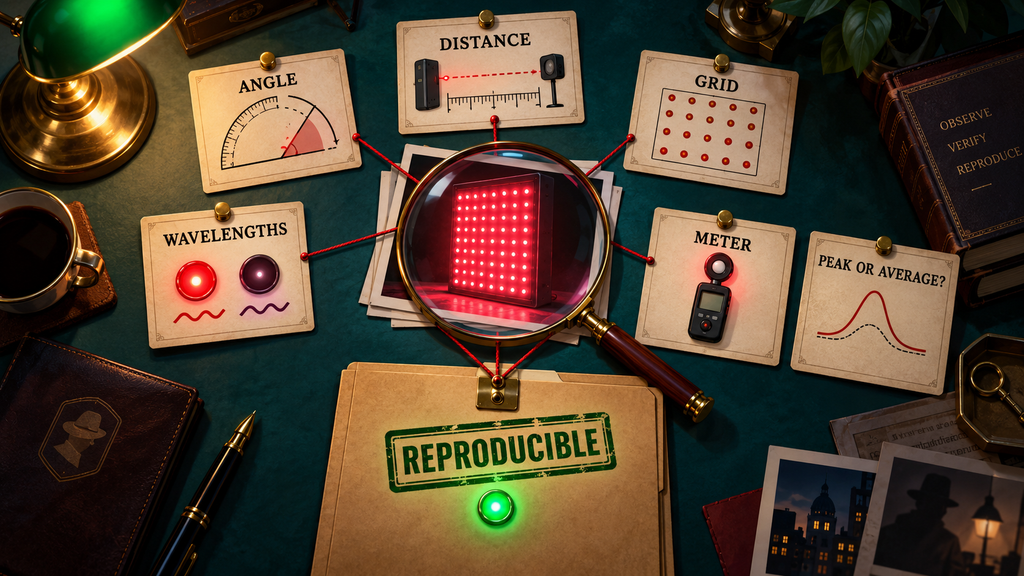
A transparent manufacturer should state the lens or beam angle, measurement distance, enabled wavelength channels, meter used, warm-up period, and whether irradiance is a peak or spatial average. A polar-intensity plot and a grid measured at practical distances are more informative than a beam-angle number alone.
Also compare panel size, LED spacing, recommended treatment distance, wavelength allocation, controls, cooling, warranty, and safety documentation. Our red light therapy device buyer’s guide provides the broader framework.
Does Beam Angle Change the Recommended Session Time?
Beam angle can influence the irradiance reaching a surface, but it should not be used alone to calculate a session. Radiant exposure is estimated from irradiance at the treatment position multiplied by time, and an application-specific protocol includes more than those two values. A manufacturer’s angle is not a substitute for measured irradiance.
Do not shorten a session simply because a product advertises narrow lenses, or lengthen it because the lenses are wide. Follow the device instructions and any qualified clinical guidance relevant to the intended use. More exposure is not automatically better, and protocols from one device cannot be transferred solely by matching a headline specification.
Questions a Good Beam-Angle Report Should Answer
Before relying on a coverage claim, check whether the report identifies the LED lens angle and its definition, the distance from the emitting face, the dimensions of the measurement plane, the spacing between sample points, the active wavelengths, and the meter model. It should explain whether the published figure is the maximum point, the mean of all points, or the minimum within a defined area. Ideally, it also reports variation after warm-up and separates red from near-infrared channels. These details turn an attractive diagram into a test another person could reproduce.
Conclusion
Red light therapy beam angle helps explain how individual LEDs spread light, but the treatment field comes from the entire array. Lens angle, LED spacing, panel dimensions, distance, orientation, and wavelength layout jointly determine coverage and uniformity.
Narrow lenses can produce a stronger on-axis peak; wider lenses can blend across a larger area sooner. The useful comparison is not “narrow versus wide” in isolation. It is the measured spatial field at the distance and settings a person will actually use. Look for a documented grid, a clear distinction between peak and average irradiance, and a defined coverage threshold.